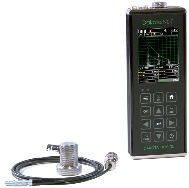
Dakota FX70 Flaw Detector (DFX-7)
Product Description
The Dakota FX70 Flaw Detector is available in two models: Dakota FX70-DL Flaw Detector and Dakota FX71-DL Flaw Detector.
Whether you are on-site or in the laboratory these gauges are the tool you need for all your flaw detecting needs.
The time corrected gain (TCG) feature automatically compensates for sound attenuation through a material, further increasing the performance of the gauge.
The Dakota FX70 Ultrasonic Flaw Detector stores up to 4GB worth of readings with A/B-scan images in alpha numeric batches with full data logging and firmware updates via USB data output to DakMaster data management software.
Features:
- Exceptional visibility in sunlight (AMOLED)
- colour VGA display (320×240 pixels)
- Sizing Toolkits: DAC, AWS, TCG, DGS
- Pulse Repetition Frequency: 8 to 2000Hz, adjustable
- Detection: Z-Cross, Flank & Peak
- Automatic: probe zero, probe recognition, and temperature compensation
- Measurement: Variety of modes to address a number of applications
- Large data storage with multiple formats: Alpha numeric grid and sequential with auto identifier
- Download to DakMaster data management software
-
Summary
Versatile 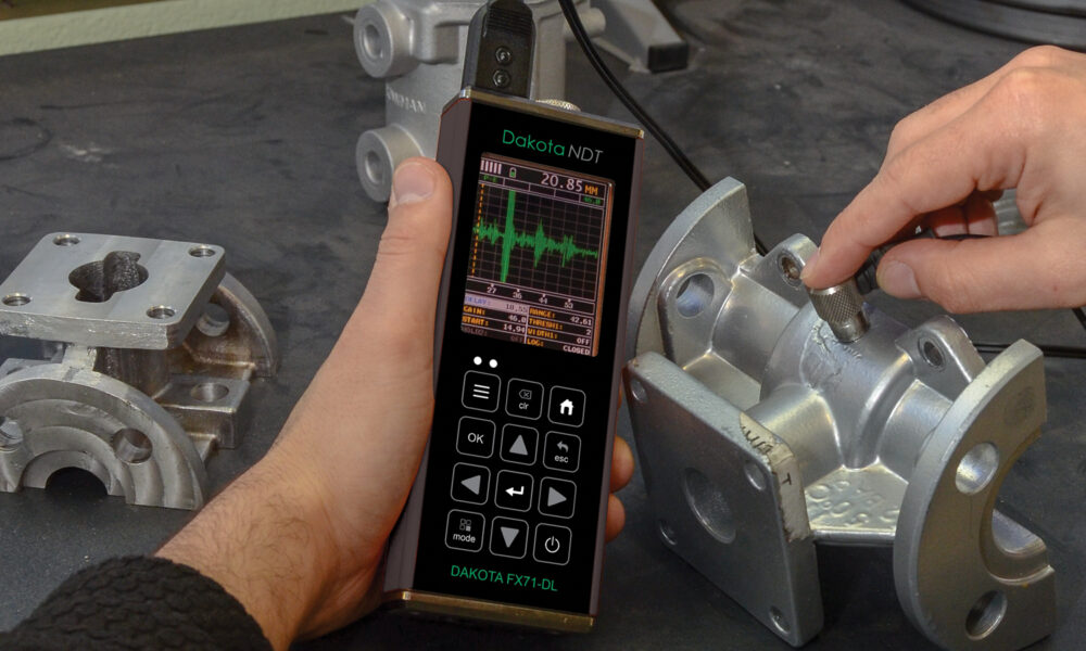
The Dakota FX70 Flaw Detector series has two functions, a thickness gauge and a flaw detector. When the Dakota FX70 Flaw Detector is set to thickness gauge it has the ability to measure coatings and material thickness simultaneously. When set to flaw detector the gauge has the ability to detect the size and position of flaws and to differentiate between flaw types in various materials and welded joints. 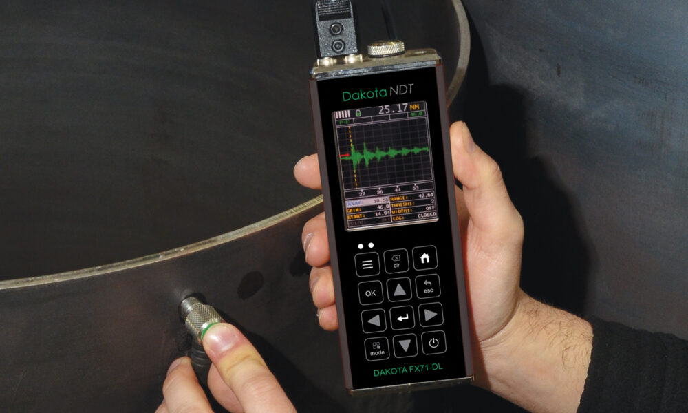
Intelligent User definable limits for pass/fail indication. Set hi/lo limits for pass/fail indication with audible warnings and built-in differential mode for quality control inspections. Powerful 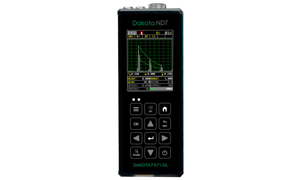
Store each measurement for further analysis. Up to 4GB of readings can be saved into the gauge memory as each measurement is taken, which can be downloaded later into an inspection application or into DakMaster™ Software for further analysis and reporting. 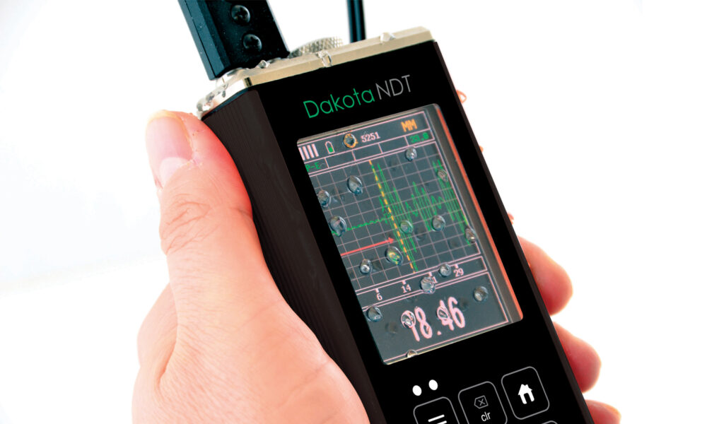
Customisable Customisable tool kits and reading display. The Dakota FX70 Ultrasonic Flaw Detector has a choice of display modes allowing the user to select the most appropriate for their needs; from A & B-Scan displays to flaw detection modes such as TRIG, DAC, TCG, Flank and Peak. Detection Methods
Zero Crossing: Flank: The gate detects the flank of the pulse, but the measurement is taken at the next crossing of the x axis. This is the most common type of detect in ultrasonic measurement. The gate is triggered by the flank (or side) of the pulse on the graph and the measurement taken at this exact point. Peak: TRIG: The gate is triggered by the intersection with the A-scan pulse and the detection is taken from the next peak in the signal (when it stops rising and starts falling). TRIG enabling location of flaws in both surface distance and depth. Trigonometric display of beam path, depth, surface distance, and curved surface correction. Used with angle beam transducers. DAC: AWS: Distance amplitude correction for the creation of DAC curves which are used to inform the operator of the size of any given flaw at any depth. The American Weld Standard function provides automatic defect sizing in accordance with AWS D1.1 structural welding code. TCG: Time corrected gain increases gain as distance increases, in order to achieve an over all level of sensitivity for the same flaw/reflector at different distances.
Product Features
| Material Thickness Features | |
| Model | FX70-DL & FX71-DL |
| Display Mode | |
| Material thickness digits display | ■ |
| B-Scan cross-sectional display | ■ |
| B-Scan with digits display | ■ |
| Scan bar display | ■ |
| Coating thickness display | ■ |
| A-Scan display | + Rectified, – Rectified, Full Waveform (RF) |
| Flaw Detection Modes | TRIG, DAC, AWS, TCG, AVG/DGS |
| Measurement Range | Pulse Echo (PE) 0.63 – 2,440mm Pulse Echo (single contact) 1.0 – 30,480mm Echo Echo ThruPaint (EE) 1.27 – 102mm Echo Echo (single delay line) 0.178 – 25.4mm Echo Echo (single contact) 1.0 – 3,050mm Echo Echo Verify (EEV) 1.27 – 25.4mm Pulse Echo Temp Comp (PETP) 0.63 – 2,440mm Coating Thickness (CT) 0.0127 – 2.54mm Pulse Echo Coating Thickness (PECT) 0.01 – 2.54mm Pulse Echo Coating Thickness (PECT) 0.63 – 2.440mm |
| Resolution | 0.01mm , 0.001mm selectable |
| Measurement Rate (Thickness Mode) | |
| Manual | 8 Readings per second |
| Scan Mode | 50 Readings per second |
| Scan bar display | 10 Readings per second |
| High Speed Scan Mode | ■ |
| Differential Mode | ■ |
| Limit alarm mode | ■ |
| B-Scan display speed | Adjustable display speed |
| Calibration setups | 64 User-definable setups transferrable to and from a PC archive |
| Gates | 2 (flaw) and 3 (thickness) adjustable gates: start, stop, width & threshold |
| Damping | 50, 75, 100, 300, 600, & 1500 ohms |
| Pulser type | Two adjustable square wave pulsers and receivers |
| Gain | Manual, automatic gain control (AGC) with 110dB range with 0.2dB resolution |
| Timing | Precision TCXO timing with single shot 100 MHz 8 bit ultra-low power digitizer |
| Memory and Data Logging | • 4GB internal memory • Sequential and grid logging • Alpha numeric batch identification • OBSTRUCT indicates inaccessible locations • Bitmap graphic capture and capture viewer |
| Data Output | USB-C |
| Calibration Options | Single, two point, velocity, material type |
| Transducer recognition | Automatic |
| V-path / dual path error correction | Automatic |
| Probe Zero | Automatic |
| Automatic Calibration | Longitudinal (straight), or Shear (angle) |
| Flaw Detection Product Features | |
| Probe Types | Single Contact, Dual, Delay & Angle |
| Material Velocity Table | Contains longitudinal and shear velocities for a variety of material types |
| TRIG | Trigonometric display of beam path, depth, surface distance, and curved surface correction. Used with angle beam transducers |
| DAC | Up to 8 points may be entered and used to digitally draw a DAC curve. Reference -2, -6, -10, (-6/-12), (-6/-14), (-2/-6/-10) dB. Amplitude displayed in %DAC, dB, or %FSH |
| AWS | Automatic defect sizing in accordance with AWS D1.1 structural welding code. |
| AVG/DGS | Automatic defect sizing using probe data. Stores up to 64 custom setups |
| TCG | Time corrected gain. 50 dB dynamic range, 20 dB per microsecond, up to 8 points for curve definition |
| Detection Modes | Zero Crossing, Flank and Peak |
| Display Freeze | Hold current waveform on screen |
| Peak Memory | Captures peak signal amplitude |
| PRF | 8 to 2000Hz in selectable steps (8, 16, 32, 66, 125, 250, 333, 1000, 2000Hz) |
| Skip Bar | Displays skip legs in the waveform area |
| Pulse Width | 40 to 400 ns. Selectable step options 40, 80 & 400 ns (labeled spike, thin & wide) |
| Frequency Bands | FX70-DL & FX71-DL: Broadband 1.8 – 19MHz FX71-DL: Three narrow bands at 2MHz, 5MHz, 10MHz |
| Horizontal Linearity | +/- 0.4% FSW |
| Vertical Linearity | +/- 1% FSH |
| Amplifier Linearity | +/- 1 dB |
| Amplitude Measurement | 0 to 100% FSH, with 1% resolution |
| Delay | 0 – 999in (25,375mm) at steel velocity |
| Display | 1/4 VGA AMOLED colour display 57.6 x 43.2mm viewable area |
| Display Refresh Rate | 60Hz |
| Units (selectable) | mm |
| Backlight | Adjustable brightness |
| Repeatability / Stability Indicator | ■ |
| Low Battery Indicator | ■ |
| Battery Save Mode | Auto |
Technical Specifications
| Part Number | Description |
| Z-220-0005 | Dakota FX70-DL Flaw Detector (DFX-7) |
| Z-221-0005 | Dakota FX71-DL Flaw Detector (DFX-7+) |
| Operating Temperature | -10 to 60ºC |
| Power Supply | 3 x AA batteries and via USB |
| Battery Life2 | Alkaline (12hrs), Nicad (5hrs), and NI-MH (12hrs) |
| Gauge Weight | 397g – including batteries |
| Gauge Dimensions | 63.5 x 165 x 31.5mm |
● Certificate of Calibration supplied as standard
Data Sheet
Standards
Thickness Gauge: Factory calibration traceable to NIST & MIL-STD-45662A.
Flaw Detector: EN12668-1 compliant.
Part Numbers
| Dakota FX70-DL Flaw Detector (DFX-7) | ||
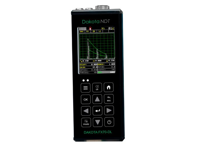 |
Part Number: | Z-220-0005 |
| Dakota FX71-DL Flaw Detector (DFX-7+) | ||
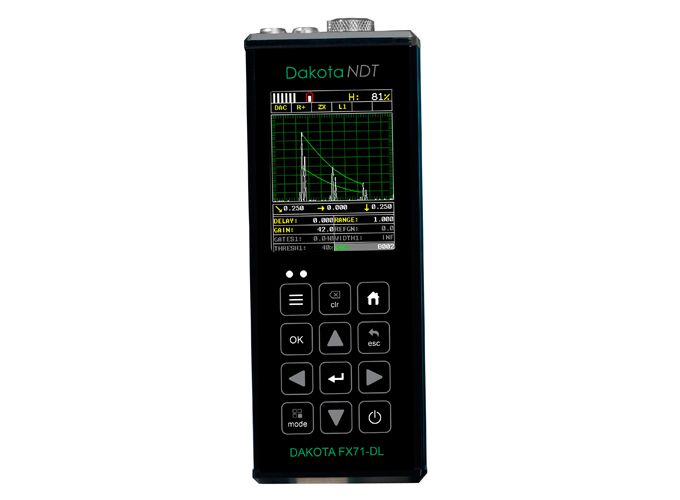 |
Part Number: | Z-221-0005 |
Packing List
| Packing List | Model | |
| Z-220-0005 | Z-221-0005 | |
| Unit | ■ | ■ |
| Selectable Transducer | ■ | ■ |
| Couplant | ■ | ■ |
| Manual | ■ | ■ |
| Plastic Carrying Case | ■ | ■ |
| Certificate of Calibration | ■ | ■ |
| AA Batteries | ■ | ■ |
| PC Software | ■ | ■ |
| Data Transfer Cable | ■ | ■ |